
This page contains affiliate links. If you purchase through these links, we may earn a small commission at no extra cost to you. Full disclosure.
Weather Station Post
One pine board becomes a standing weather house. It reads temperature and humidity on a screen — then grows a soldering iron and two more sensors when your builder is ready.
Jump to Materials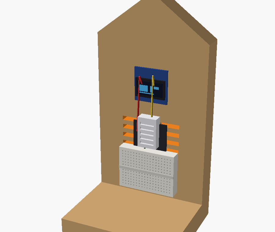
One pine board becomes a standing weather house. It reads temperature and humidity on a screen — then grows a soldering iron and two more sensors when your builder is ready.
Measuring, sawing, drilling, and finishing real wood; power, ground, data pins, pull-up resistors, and I2C bus; why pressure predicts storms; soldering (Level 2); reading sensors and coding a display; data logging and spotting trends
Active supervision recommended
Materials List
- Pine 1×4 offcut (~12 inches) $3 View
- ESP32 dev board $8 View
- 0.96" OLED display (I2C) $4 View
- DHT22 temperature + humidity sensor $4 View
- Half-size breadboard $2 View
- Jumper wires (M-M / M-F pack) $2 View
- 10 kΩ resistor (pull-up for DHT data) $0.10 View
- USB cable + 5 V phone charger $5 View
- BMP280 pressure sensor (Level 2) $3 View
- BH1750 light sensor (Level 2) $3 View
- Perfboard + hook-up wire + heat-shrink (Level 2) $4 View
Tools Needed
An adult handles or closely supervises the saw and drill. Clamp the work, cut away from hands, and wear eye protection. Sand every edge a young builder will touch. Soldering (Level 2 only): iron reaches 350°C+ — use a stand, heat-safe mat, and good ventilation; tie back hair; never leave a hot iron unattended. Runs on a standard 5 V USB phone charger — low voltage and safe.
What You’re Building
A weather station is a perfect first “one board plus a brain” project. The wood gives you a real thing to cut, drill, sand, and paint, and the electronics turn it into something that actually does something useful on the windowsill.
You build it in two levels:
- Level 1 (Beginner): No soldering. Everything pushes together on a breadboard. An adult supervises the saw and drill; the child does the wiring. Reads temperature and humidity.
- Level 2 (Advanced): Soldering. Rebuild permanently on a soldered board and add two more sensors — barometric pressure for forecasting, and light brightness.
Part of the One-Board Builds series — one board, no joinery, one real circuit.
The One Board — Cut List
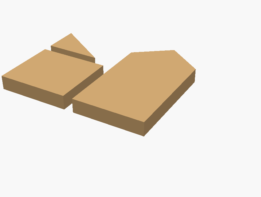
From a single pine 1×4 offcut, cut three pieces:
- Base — flat foot it stands on
- Front panel — tall piece with a roof peak (two angled cuts)
- Brace — small triangle that keeps it upright
Then drill: a rectangular display window near the top, a band of vent slots so outdoor air reaches the sensor, and one cord hole at the base for the USB cable.
Level 1: Beginner Build
Step 1: Start With One Board
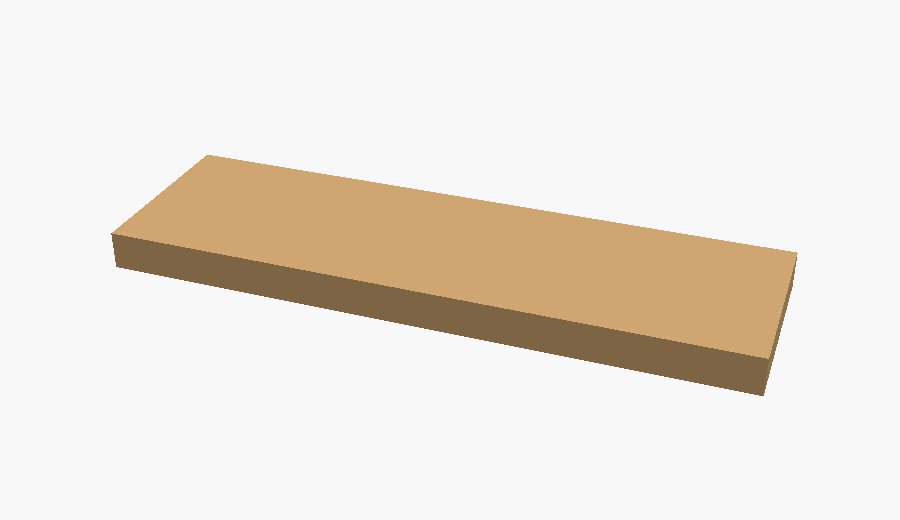
A single pine 1×4 offcut is the whole enclosure. Sand the faces and knock the sharp edges off before anything else.
Step 2: Cut Three Pieces
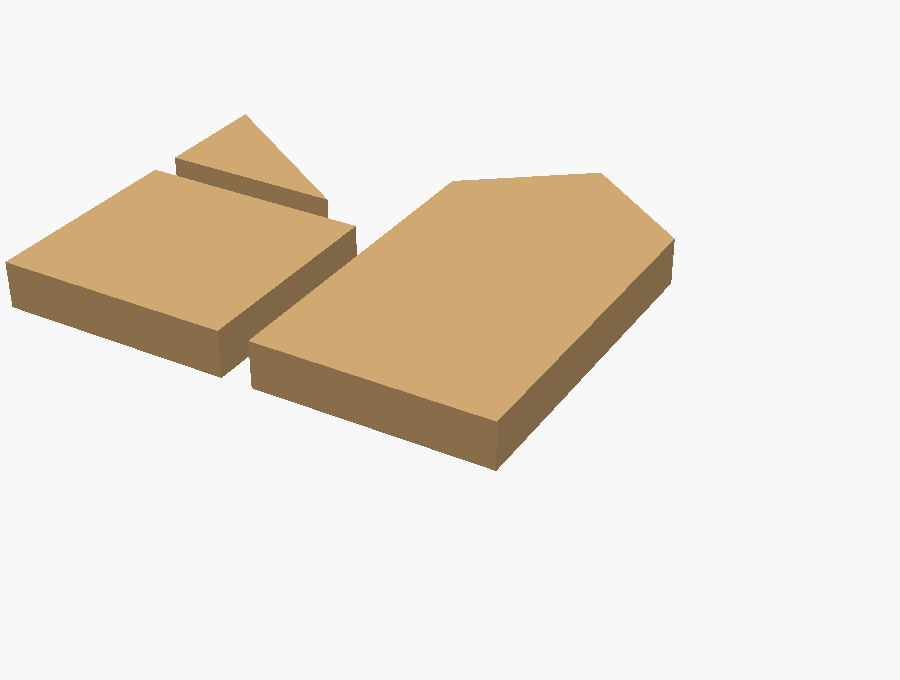
From that one board: a base to stand on, a tall front panel (cut the roof peak with two angled cuts), and a small triangular brace. That’s every wooden part.
Step 3: Drill the Window, Vents & Cord Hole
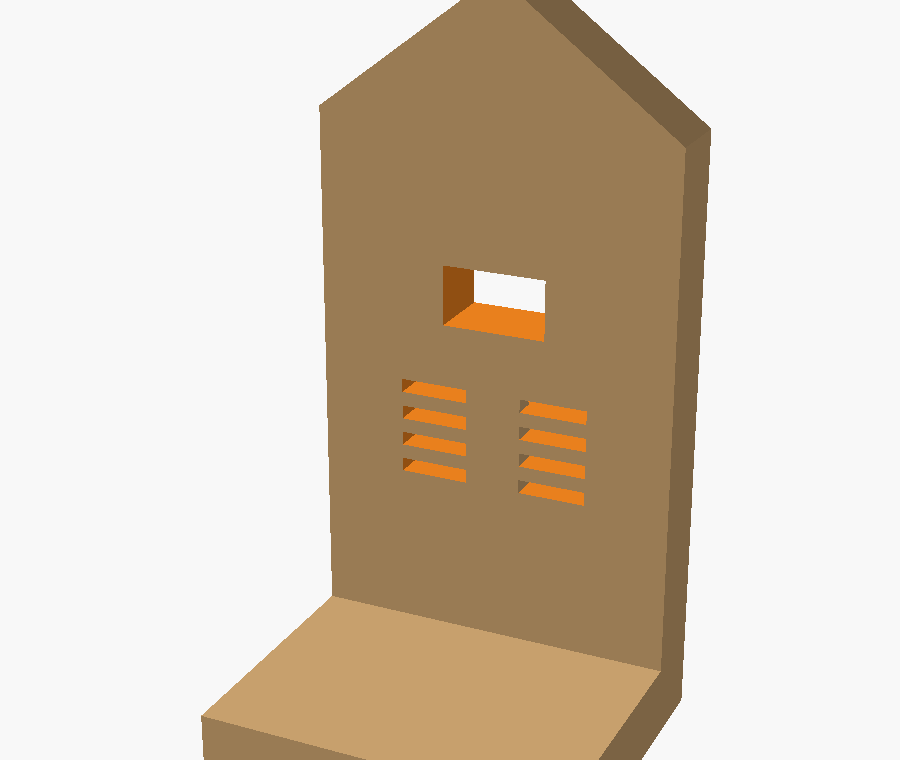
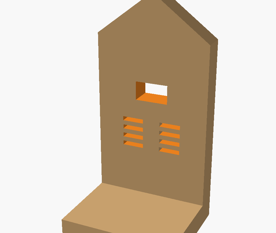
Cut a rectangular window for the display near the top. Drill or chisel a band of vent slots in the middle so outside air reaches the sensor. Add one cord hole at the base for the USB cable.
Step 4: Assemble the Stand
Screw the front panel upright onto the base, then add the brace behind it so it can’t tip. Paint or seal it now if you want — let it dry fully before adding electronics.
Step 5: Add the Electronics
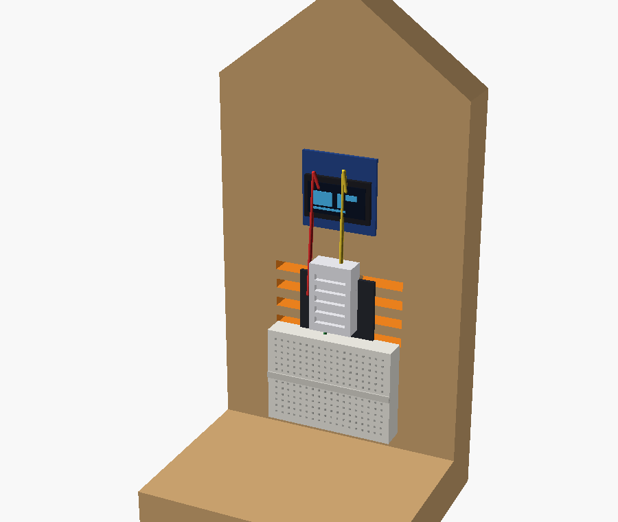
Press the ESP32 into the breadboard, mount the OLED behind the window and the DHT22 behind the vents, then run the jumper wires shown in the diagram. Plug in the USB and readings appear.
Level 1 Wiring
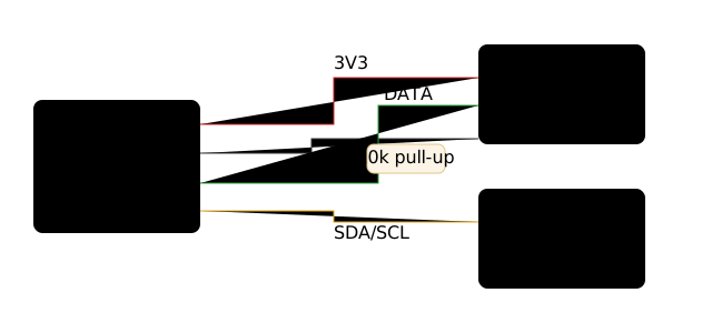
Three connections do it all: power (3V3 + GND), one data pin for the DHT22, and the two I2C lines (SDA/SCL) for the screen.
Level 1 Code
Flash the ESP32 with a starter sketch (Arduino IDE or MicroPython) that reads the DHT22 and prints temperature and humidity to the OLED. Beginners can start from a ready-made example and just change the wording on screen — a gentle first taste of code.
Level 2: Advanced Upgrade
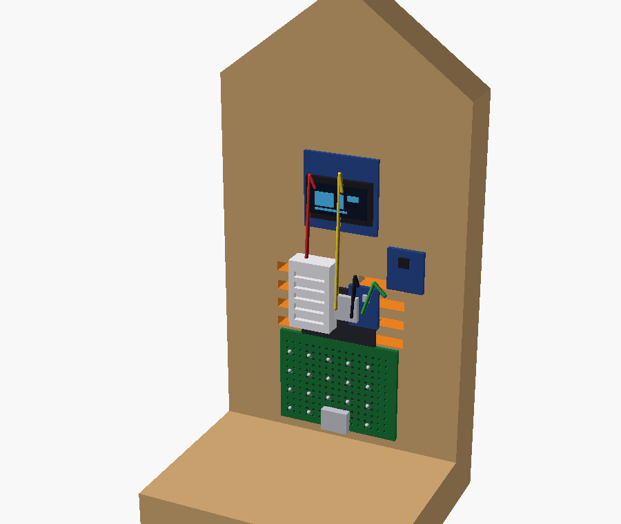
Step 1: Move From Breadboard to Soldered Board
Swap the breadboard for a protoboard and solder each part down. Connections stay put when the post gets bumped or moved outside — this is the skill the whole series builds toward.
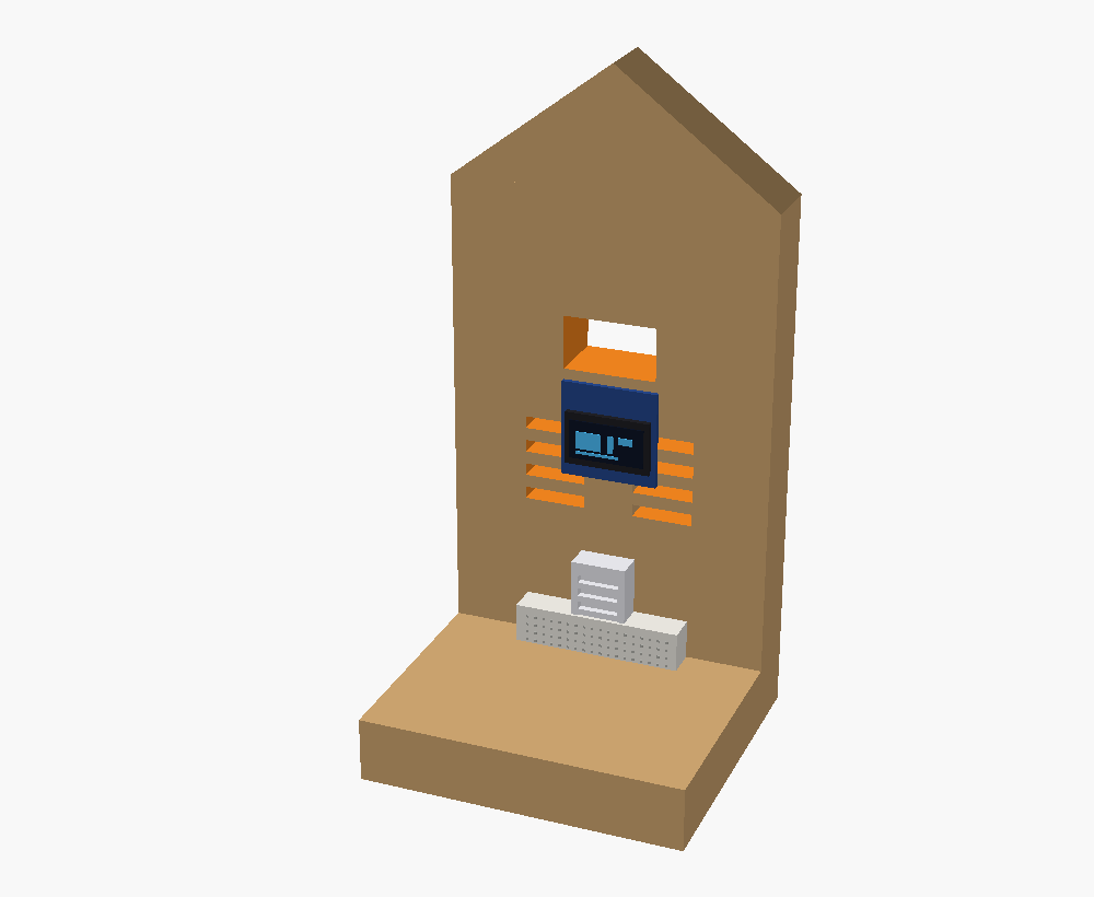
Step 2: Add the Pressure Sensor
Wire a BMP280 onto the same two I2C lines as the OLED (they share the bus, each has its own address). Barometric pressure is what lets the station actually predict weather, not just report it.
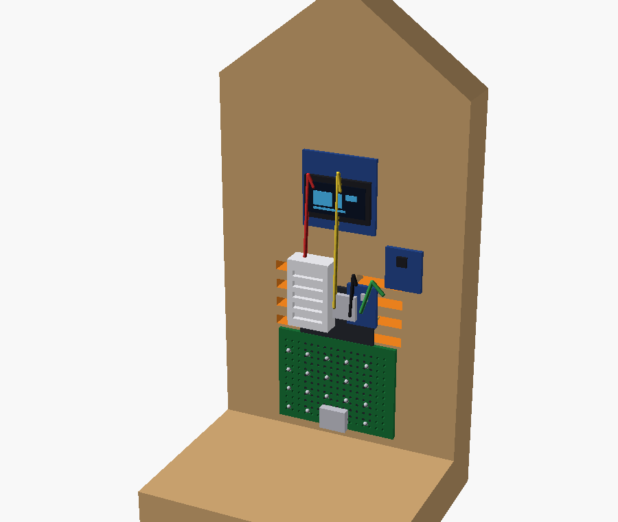
Step 3: Add the Light Sensor & Finish
Add a BH1750 for daylight brightness on the same bus. Tidy every joint with heat-shrink, seal the wood against moisture, and it’s ready for a covered porch.
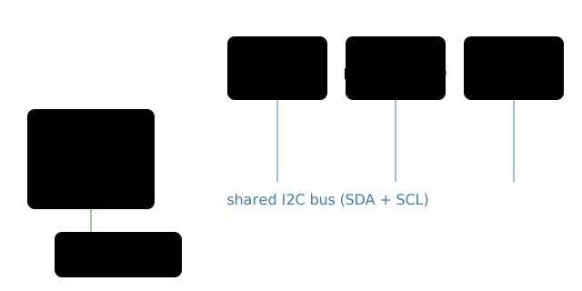
Level 2 Wiring
The magic of I2C: the OLED and both new sensors share the same two wires. Each has its own address (OLED 0x3C, BMP280 0x76, BH1750 0x23), so the ESP32 talks to them one at a time.
Level 2 Code
The sketch now reads four values and can do something smart: compare pressure over a few hours and print “steady / rising / falling” — a real, simple forecast.
Stretch Goal: Connected Station
The ESP32 has WiFi built in. Once the sensors work, have an older builder push the readings to a phone or a tiny web page on your home network — the station becomes something you can check from another room, or graph over a week.
Make It Easier
- Ages 7–12 (Level 1): Breadboard weather post — cut, drill, wire, and watch live temperature and humidity on the screen. No soldering, no code required — start from an example sketch.
Make It Harder
- Ages 12–18 (Level 2): Rebuild it to last, learn to solder, and add pressure and light sensors on a shared I2C bus. Tweak the code to show a steady/rising/falling trend.
- Stretch: Use the ESP32’s WiFi to send readings to your phone or a home web page. Log over time and graph the week.
Troubleshooting
| Problem | Fix |
|---|---|
| Screen stays black | SDA/SCL swapped, or wrong I2C address. Swap the two data wires; try address 0x3C then 0x3D in code. |
| Temperature reads “nan” | Missing pull-up, or wrong data pin. Add the 10 kΩ resistor from data to 3V3; confirm pin number in code. |
| Readings look too warm | ESP32’s own heat reaching the sensor. Mount the DHT22 out at the vents, away from the board. |
| Nothing powers on | Cable is charge-only, or dead port. Use a known data USB cable and a 5 V charger; check the board’s power LED. |
| Pressure sensor not found | Address clash or loose solder joint (L2). Re-flow the joint; BMP280 is usually 0x76 (sometimes 0x77). |
What Your Kid Learns
Measuring, sawing, drilling, and finishing real wood; power, ground, data pins, pull-up resistors, and I2C bus; why pressure predicts storms; soldering (Level 2); reading sensors and coding a display; data logging and spotting trends